<body> this is my territory of my DNT assignment !! strictly no copiers !! <body>
Welcome
all my fellow friends ...

1. Strictly NO Copying
2. Strictly NO Spamming
3. NOT happy?!click the red X button on the right corner
Profile

name : Huiting
birthdate : 280294
school : HuaYiSecondarySchool
Class: 2E2


Thursday, May 1, 2008

How To Keep Safety In A Workshop...


How To Use A Strip Heater...


Rotary/Linear motion

Mechanisms: Crank and Slider
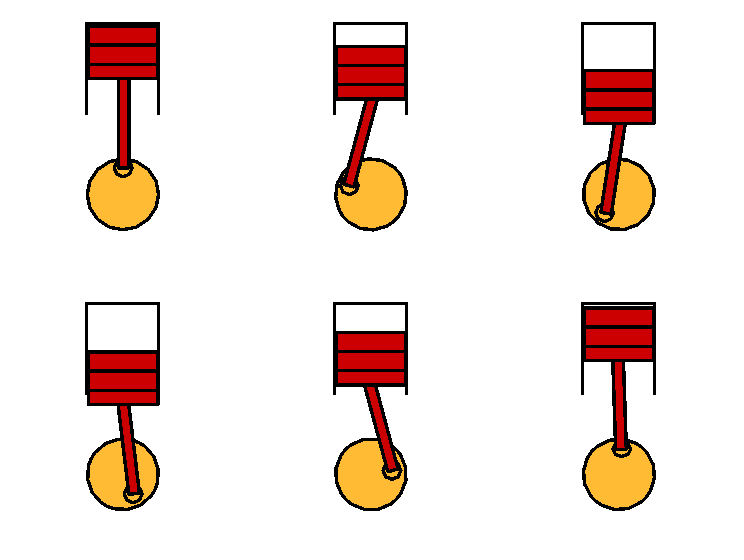
A crank and slider mechanism changes rotary to reciprocal motion or vice versa. In the car engine (illustrated) the reciprocating motion of the piston caused by exploding fuel is converted into rotary motion as the con-rod moves the crankshaft around. An air compressor uses this principal in reverse - an electric motor turns the crankshaft and the piston moves up and down to compress the air.


Mechanisms: Quick return mechanism
The 'Whitworth' quick return mechanism converts rotary motion into reciprocating motion, but unlike the crank and slider, the forward reciprocating motion is at a different rate to the backward stroke. At the bottom of the slotted arm, the peg only has to move through a few degrees to sweep the arm from left to right, but it takes the remainder of the revolution to bring the arm back. This mechanism is most commonly seen as the drive for a shaping machine.

Mechanisms: Cams and Followers
The cam and follower is a device which can convert rotary motion into linear motion (movement in a straight line). A cam is a specially shaped piece of material, usually metal or hard wearing plastic, which is fixed to rotating shaft. The cam can have various shapes eg. round, oval, heart shaped. A follower is a mechanism which is designed to move up and down as it follows the edge of the cam.Many machines which have moving parts use cams. A good example is the motor car engine which has cams to open and close valves and contact breaker points and operate fuel pumps.


Mechanisms: Rotary Cams
There are several different types of cam but most of these can be placed into two groups - rotary and linear. Rotary cams change rotary motion into reciprocating (backwards and forwards) motion. As the cam rotates, the follower moves accordingly. The exact distance it moves depends on the shape of the cam.


Bead Blasting
Bead Blasting is a process by which abrasive grits are blasted on to the surface of a material using compressed air. The effect is to gouge away the surface where it is exposed. Stencils can be cut from self-adhesive vinyl to control where the grit will abrade the surface. Different types of grit can produce effects on different materials.
Stencils can be accurately produced using a CNC vinyl cutter and a 100mm mirror tile provides a suitable surface to receive an embossed design. The embossed tile can be used as a feature of several projects including: clocks, box lids and make-up mirrors.

The vinyl stencil is stuck on to the surface of the mirror and abrasive grit is air blasted on to it. Designs which are cut into the stencil are transferred in to the surface of the mirror. Good detail can be achieved but very complicated stencils are difficult to handle quickly.


Injection Moulding
CNC milling machines provide an excellent way of manufacturing precise moulds for use in injection moulding. This project uses the equipment provided in the TEP injection moulding kit to inject plastic from a glue gun into a mould made on a CNC machine.
The mould is made from a plastic material called Tufset. This plastic machines well and can withstand the temperatures involved in the process. The billet (uncut material we start with) is 100mm wide, 50mm high and 10mm deep. It has 6mm diameter mounting holes along the centerline 82mm apart to allow it to be quickly mounted on the cnc machine and also to mate up with the TEP injection moulding equipment.

Glue enters the mould as shown in the diagram below, and air escapes through a breather hole. The design must allow glue to flow easily to all areas and allow hot air to escape through the breather. The design should not go too close to the mounting holes, as the cutting tool might foul on the bolts which are holding the work piece to the milling machine. There should be no narrow passages which would constrict the flow of the glue.

In practice, the width of passage which can be cut is limited by the smallest tool available on the CNC machine, in this case 2mm diameter. You should be aware that the CNC machine cannot cut sharp internal corners - the diameter of the radius in the corner again matches that of the smallest tool. Sharp external corners, however, are possible.


My Mechanical Toy !!!


...View From The Top

... And By The Side


My Mechanical Toy

It actually works!!!